Views: 0 Author: Site Editor Publish Time: 2026-09-15 Origin: Site
Accurate hydrocarbon detection is a non-negotiable requirement for regulatory compliance, environmental protection, and process integrity in fluid-heavy industries. Relying on delayed laboratory sampling or selecting the wrong inline detection technology leads to undetected oil spikes, false alarms from background turbidity, regulatory fines, and severe equipment fouling. Understanding the underlying physics of how an oil in water sensor operates—whether through fluorescence, light scattering, or acoustics—is necessary for engineering and procurement teams. You must match the right detection mechanism to your specific fluid matrix and compliance mandates. This guide breaks down the core mechanics of hydrocarbon monitoring. We evaluate different optical and non-optical technologies, outline specific application requirements, and provide actionable strategies to mitigate common implementation risks like optical fouling and background interference.
Technology Matching is Matrix-Dependent: Ultraviolet fluorescence excels at detecting dissolved and emulsified oils (like PAHs and VOCs), while light scatter and IR technologies are better suited for free-floating oil concentrations.
Fouling is the Primary Failure Mode: Opting for a self-cleaning oil-in-water sensor drastically reduces maintenance overhead and prevents calibration drift caused by optical window scaling.
Regulatory Alignment Dictates Selection: Marine and industrial applications require specific certifications (e.g., MARPOL MEPC.107(49) or EPA methods) which dictate the acceptable sensor architecture and reporting capabilities.
Inline vs. Extractive Trade-offs: Direct inline measurement offers real-time responsiveness, while bypass/extractive systems provide better control over sample conditioning and bubble mitigation.
To achieve reliable continuous monitoring, a sensor isolates the specific signature of oil molecules from background water, suspended solids, and chemical additives. Water streams in industrial environments carry a complex mixture of particulates, entrained air, and varying chemical compositions. Identifying hydrocarbons within this matrix requires precise physical and chemical differentiation.
The primary challenge in hydrocarbon detection is signal isolation. Sensors must distinguish between actual oil droplets and other materials that mimic oil's physical properties. A gas bubble scatters light in a way that resembles a free-floating oil droplet. High concentrations of suspended solids block optical transmission entirely. A successful monitoring system filters out these interferences. It delivers a clean, accurate signal reflecting only the hydrocarbon content. Field engineers evaluate success based on response time, accuracy against laboratory benchmarks, and the system's ability to maintain calibration over extended periods without manual intervention.
Achieving this isolation requires understanding the fluid dynamics within the pipe. Flow velocity impacts how oil disperses in water. Low velocities allow oil to float to the top of the pipe, creating stratification. High velocities shear the oil into microscopic droplets, creating a tight emulsion. The sensor must be positioned and calibrated to account for these hydraulic realities to capture a representative sample of the entire fluid volume.
Before selecting a technology, define the exact measurement goal. Different regulatory and operational scenarios demand fundamentally different sensor architectures. Understanding the chemical composition of the target oil is the first step. Aliphatic hydrocarbons behave differently under optical analysis than aromatic hydrocarbons.
Total Oil Concentration: Measures the overall amount of various oil pollutants, including both aliphatic and aromatic hydrocarbons. This measurement is standard for general wastewater discharge monitoring where regulators track the total volume of organic pollution.
Specific Toxic Compounds: Targets specific hazardous molecules like Polycyclic Aromatic Hydrocarbons (PAHs) or Volatile Organic Compounds (VOCs). Environmental agencies require this for sensitive watershed discharges because these specific compounds carry high toxicity risks.
Surface Oil Spill Detection: Identifies floating oil sheens on the water surface rather than dissolved or suspended droplets within the water column. This requires non-contact optical or radar technologies mounted above the water level.
Most modern inline sensors rely on optical baselines. They interact with the fluid stream by emitting specific light wavelengths. The sensor measures the resulting absorption, scattering, or fluorescence to quantify parts-per-million (ppm) or parts-per-billion (ppb) concentrations. Optical systems offer high sensitivity and rapid response times. They are the industry standard for trace detection.
Conversely, non-optical systems use ultrasonic frequencies or capacitance measurements. These technologies detect density variations or dielectric differences between water and hydrocarbons. Non-optical methods excel in highly opaque fluids where light cannot penetrate. They provide robust data in heavy sludge or crude oil applications where optical windows would immediately blind.
Selecting the correct detection technology depends entirely on the physical state of the oil and the composition of the carrier fluid. No single technology handles every type of hydrocarbon pollution equally well. Engineering teams must match the physics of the sensor to the chemistry of the process.
An ultraviolet fluorescence oil-in-water sensor provides unmatched sensitivity for specific hydrocarbon types. The sensor emits a targeted beam of ultraviolet light, typically around the 254 nm or 365 nm wavelengths, into the water stream. When this UV energy strikes aromatic hydrocarbons, the molecules absorb the light and enter an excited energy state. As they return to their ground state, they emit light at a longer wavelength, usually between 300 and 400+ nm. A highly sensitive photodetector captures this emitted light. The intensity of the fluorescence is directly proportional to the concentration of oil in the water.
This technology is highly effective for detecting dissolved oils, PAHs, VOCs, and trace amounts of toxic crude or refined fuels. It easily measures concentrations in the low ppb range. Fluorescence is valuable in complex matrices because most naturally occurring suspended solids do not fluoresce at these specific wavelengths. This natural physical filtering allows the sensor to ignore background dirt and focus purely on the hydrocarbon content. However, it requires the presence of aromatic compounds to function; pure aliphatic oils like mineral oil will not fluoresce and remain invisible to this technology.
Infrared and light scatter technologies focus on physical interaction rather than molecular excitation. Infrared sensors measure the absorption of specific IR wavelengths by carbon-hydrogen bonds. Every oil molecule possesses a specific absorption spectrum, often peaking around the 3.4-micrometer range for C-H stretching. By calculating the amount of IR light absorbed as it passes through the sample, the sensor determines the oil concentration.
Light scatter sensors project a light beam into the fluid and measure the angle and intensity of light scattered by suspended particles. Oil droplets scatter light at different angles compared to solid sand or rust particles. These methods are best for measuring total free oil and higher concentration emulsions. Fluorescence sensors saturate at high ppm levels, making IR and light scatter better suited for gross contamination monitoring, heavy industrial effluents, and bulk oil-water separation processes.
For highly specialized environments, microscopy and acoustics offer unique advantages. Microscopy relies on high-speed digital image recognition. A camera captures thousands of frames per second, and an integrated algorithm categorizes droplet sizes and shapes in real-time. Ultrasonic acoustic methods send high-frequency sound waves through the fluid. The system analyzes the acoustic impedance and velocity changes caused by density variations between water, oil, and gas.
These are niche solutions for environments requiring strict differentiation between oil droplets, gas bubbles, and solid particles. Microscopy is used in research or complex separation optimization. Acoustic sensors perform exceptionally well in heavy crude applications where optical windows would immediately foul and blind standard optical probes.
Technology | Primary Target | Strengths | Limitations |
|---|---|---|---|
UV Fluorescence | Dissolved oils, PAHs, VOCs | Extreme sensitivity (ppb), naturally ignores most suspended solids | Struggles with pure aliphatic oils, can saturate at high ppm levels |
Infrared (IR) Absorption | Total free oil, heavy organics | Identifies specific C-H bonds, highly accurate for total oil mass | Water absorbs IR heavily; often requires complex sample conditioning |
Light Scatter | Emulsions, free-floating droplets | Excellent for gross contamination and high ppm ranges | Highly susceptible to interference from gas bubbles and turbidity |
Ultrasonic Acoustic | Heavy crude, opaque fluids | Immune to optical fouling, works in zero-visibility fluids | Lower sensitivity compared to optical methods, requires density contrast |
The operational environment dictates sensor performance. A device that works flawlessly in a clean cooling loop fails within hours in a raw wastewater trench. Engineering teams evaluate the specific physical and chemical stressors of their application before deployment.
Deploying an industrial wastewater oil content sensor requires robust engineering. The sensor must handle high turbidity, variable pH levels, and diverse chemical cocktails. Industrial effluents contain coagulants, flocculants, and heavy metals that severely interfere with optical readings. The system must differentiate between actual hydrocarbon pollution and harmless background matter to prevent false positives.
Alignment with local municipal discharge limits and EPA continuous monitoring standards is mandatory. Facilities maintain strict data logs to prove compliance during unexpected audits. The sensor provides verifiable, repeatable data that correlates closely with approved laboratory extraction methods, such as EPA Method 1664. Bridging the gap between continuous inline monitoring and periodic grab-sample lab analysis requires a sensor capable of algorithmic compensation for background noise. Field technicians often install secondary turbidity sensors alongside the oil monitor to provide real-time baseline corrections.
Marine environments present harsh conditions for instrumentation. A marine bilge water oil sensor withstands extreme vibration, high salinity, and severe shipboard environmental stressors. The rolling and pitching of a vessel introduces massive amounts of entrained air into the bilge water lines. This requires advanced bubble-rejection algorithms to prevent light scatter from triggering false high-oil alarms.
Strict adherence to IMO/MARPOL regulations is required globally. Specifically, the MEPC.107(49) standard mandates continuous monitoring of oil-water separator discharges. The system triggers a fail-safe alarm and automatically halts the overboard discharge if the oil concentration exceeds 15 ppm. Tamper-proof data logging is a strict regulatory requirement for marine vessels to prevent illegal dumping and ensure transparency during port state control inspections. The hardware must feature secure enclosures and encrypted memory modules to satisfy maritime inspectors.
Industrial cooling systems require early warning capabilities to prevent catastrophic damage. Sensors need high sensitivity to trace hydrocarbons in closed-loop cooling systems. Minor pinhole leaks in a refinery heat exchanger introduce lubricating oils or process hydrocarbons into the cooling water. Because cooling water is typically clean, optical transmission is high, allowing for extreme sensitivity.
The operational goal is providing immediate alerts to mechanics and plant operators regarding oil ingress. Detecting a leak at the ppb level allows maintenance teams to schedule repairs during planned downtime. This enables preventative maintenance before catastrophic equipment failure occurs, preventing massive system contamination, environmental release, and costly production halts. Installation in these environments usually involves inserting the probe directly into the main return header to capture the mixed flow from all upstream heat exchangers.
Remote and unmanned facilities rely heavily on automated data collection. An online oil pollution monitoring sensor offers seamless integration capabilities with plant SCADA or DCS systems. Standard communication protocols via 4-20mA, Modbus RTU, or HART are essential for reliable data transmission across large industrial footprints.
Real-time data logging, automated alarm triggers, and remote diagnostic capabilities are operational priorities. Operators monitor sensor health, check calibration status, and acknowledge alarms from a central control room without dispatching personnel to the field. Advanced sensors provide internal diagnostics that flag when optical windows require cleaning or when light sources begin to degrade, shifting maintenance from reactive to predictive. This remote visibility is highly valuable for offshore platforms and isolated pumping stations where physical access is limited.
Hardware specifications only tell part of the story. Long-term reliability depends heavily on how the sensor manages physical fouling and electronic drift in the field. Without proper maintenance features, even the most advanced optical system becomes useless within days.
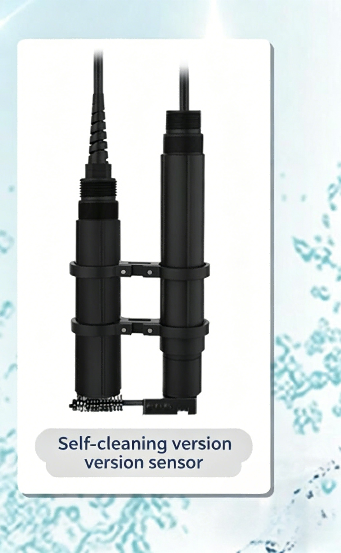
Optical sensors are highly susceptible to fouling. Biofilms, mineral scaling, and the oil itself quickly coat the optical window, blinding the sensor and causing severe signal drift. A self-cleaning oil-in-water sensor utilizes automated systems to maintain optical clarity without human intervention.
Common cleaning mechanisms include ultrasonic cleaning transducers that generate microscopic cavitation bubbles to continuously scrub the lens surface. Mechanical wipers physically sweep debris away at programmed intervals. Pneumatic air blasts or clean water flushes clear heavy sludge from the measurement chamber. This automation minimizes manual intervention. It prevents signal degradation from biofouling or oil filming. By keeping the optics clean, the sensor maintains its baseline accuracy, lowering overall maintenance burdens and operational downtime. Wipers require periodic blade replacement, usually every six to twelve months, depending on the abrasiveness of the suspended solids in the fluid.
All sensors experience drift over time due to component aging, temperature fluctuations, or environmental shifts. Facilities choose between factory pre-calibration and site-specific calibration. Factory calibration uses standard oils, providing a good baseline for general monitoring. Site-specific calibration using the actual target oil from the process stream yields much higher accuracy. Different oils have different fluorescence and absorption characteristics. A sensor calibrated for marine diesel reads differently if exposed to heavy fuel oil.
Proper calibration management ensures long-term accuracy and determines the required frequency of routine maintenance checks. Advanced sensors feature internal reference diagnostics. These systems monitor light source degradation and automatically compensate for minor electronic drift, extending the time between physical calibrations and ensuring the data remains trustworthy. Technicians perform zero-point calibrations using clean, oil-free water and span calibrations using a known concentration of the target hydrocarbon.
Maintenance Task | Standard Sensor Frequency | Self-Cleaning Sensor Frequency | Field Action Required |
|---|---|---|---|
Optical Window Cleaning | Weekly / Bi-weekly | Automated (No manual action) | Remove probe, wipe with solvent, reinstall. |
Zero Calibration Check | Monthly | Quarterly | Flush chamber with clean water, reset baseline. |
Span Calibration | Quarterly | Bi-Annually | Introduce known oil sample, adjust gain settings. |
Wiper Blade Replacement | N/A | Annually | Unbolt wiper assembly, replace rubber blade. |
No single technology is perfect for every application. Engineering teams navigate several conceptual trade-offs during the design and procurement phase to avoid costly field failures. Proper installation geometry and sample conditioning are just as important as the sensor hardware itself.
Suspended solids, gas bubbles, or naturally occurring fluorescent organic matter (CDOM) trigger high-oil alarms. This leads to operator fatigue, where staff ignore warnings because the system cries wolf too often. Utilizing dual-wavelength sensors helps differentiate between target hydrocarbons and background organics. Installing bubble-trap sample conditioning systems physically removes entrained air by reducing fluid velocity and allowing air to vent before the fluid reaches the measurement chamber. Algorithmic compensation uses secondary turbidity or temperature sensors to mathematically correct the primary oil reading in real-time.
Direct inline measurement involves inserting the probe directly into the main process pipe. This offers immediate real-time responsiveness and lower installation costs since no additional plumbing is required. It is harder to isolate for maintenance without shutting down the entire process line. Bypass or extractive systems divert a small sample stream through a separate measurement chamber. This requires additional pumps, valves, and plumbing. It provides vastly better control over sample conditioning, flow rate regulation, and allows for easier calibration access without interrupting the main process flow.
Installation Type | Pros | Cons |
|---|---|---|
Inline (In-Situ) | Zero sample lag time, lower upfront piping costs, no secondary pumps needed. | Requires process shutdown for maintenance, highly susceptible to main-line pressure spikes. |
Bypass (Extractive) | Easy isolation for calibration, allows for bubble traps and flow regulators. | Higher installation complexity, introduces slight measurement delay, requires sample return line. |
High-sensitivity sensors operating in the ppb range sacrifice the ability to measure gross oil spills in the high ppm or percentage range. Once the oil concentration exceeds a certain threshold, the optical receiver becomes saturated, and the reading flatlines. Wide-range sensors designed for heavy contamination lack the resolution to detect minor trace leaks. Selecting the appropriate dynamic range requires analyzing the expected baseline conditions versus potential upset conditions. If a facility needs to monitor trace leaks but also requires gross spill detection, they deploy two different sensor types in series to cover the entire spectrum.
To finalize your sensor selection and ensure continuous compliance, execute the following steps:
Audit your current discharge parameters to define your exact ppm or ppb detection requirements based on local environmental regulations.
Request sample testing or pilot programs from manufacturers using your specific process water to verify sensor accuracy against background interference.
Evaluate the maintenance requirements of self-cleaning models against standard probes to ensure long-term reliability and minimal manual intervention.
Verify that your chosen communication protocols integrate seamlessly with your existing SCADA or DCS infrastructure for automated alarming and remote diagnostics.
A: These sensors detect hydrocarbons from the low parts-per-billion (ppb) range up to low parts-per-million (ppm) levels. Their extreme sensitivity relies entirely on the presence of aromatic hydrocarbons and VOCs within the oil. Because they measure molecular excitation, they identify trace contamination long before it becomes visible to the naked eye.
A: It uses automated mechanisms to continuously remove biofilms, scale, and oil residue from the optical window. Common methods include ultrasonic transducers that create microscopic scrubbing bubbles, or mechanical wipers that physically sweep the lens. This prevents signal degradation and ensures continuous accuracy without manual scrubbing.
A: Yes. Advanced sensors use multiple light angles, dual-wavelength fluorescence, or secondary turbidity measurements to distinguish hydrocarbons from inert suspended solids. By analyzing how light interacts specifically with aromatic compounds or oil droplet boundaries, the sensor mathematically filters out the interference caused by solid particulates.
A: Under the IMO MARPOL MEPC.107(49) standard, marine sensors must continuously monitor oil-water separator discharges. The system must trigger a fail-safe alarm and automatically stop the overboard discharge if the oil concentration reaches or exceeds 15 ppm. It also requires tamper-proof data logging to verify compliance during port inspections.
A: Calibration frequency depends heavily on the technology and the process environment. Standard optical probes require monthly checks. Self-cleaning models that prevent optical fouling and utilize internal reference diagnostics extend calibration intervals from a few weeks to several months, drastically reducing maintenance workloads.
A: False readings are primarily caused by entrained air bubbles scattering light, high turbidity blocking optical transmission, and non-target fluorescent chemicals mimicking hydrocarbons. Mitigation strategies include installing mechanical bubble traps, using dual-wavelength optical filtering, and applying algorithmic compensation based on secondary turbidity sensors.
A: An oil-in-water sensor detects hydrocarbon pollution suspended or dissolved in aqueous streams. Water-in-oil sensors provide early warnings for preventative maintenance by detecting moisture contamination in lubrication, hydraulic, or coolant fluids. They use capacitive technologies to measure changes in the oil's dielectric constant caused by water ingress.