
Views: 0 Author: Site Editor Publish Time: 2026-10-09 Origin: Site
High-pressure aviation hydraulic systems demand absolute reliability. Unmonitored component wear can rapidly escalate from localized degradation into catastrophic failure. We know reactive maintenance falls short in these critical flight environments. Instead, proactive wear debris monitoring serves as a vital safeguard. The magnetic chip detector for aviation hydraulic systems acts as the industry-standard frontline defense. It captures and identifies ferromagnetic particles long before a major mechanical breakdown occurs. This guide equips maintenance directors and procurement engineers with a clear, evidence-based framework. You will learn how to properly evaluate, select, and implement these essential monitoring tools. We will explore capture efficiency, flow dynamics, and system integration strategies. By mastering these concepts, you can confidently protect your aircraft hydraulic networks. You will reduce unscheduled maintenance events and enhance overall flight safety across your fleet operations.
Early Fault Detection: Magnetic chip detectors provide critical, deterministic evidence of ferromagnetic wear, isolating hydraulic component degradation earlier than bulk fluid analysis.
Evaluation Priorities: Selection must prioritize capture efficiency, flow dynamics, and the reduction of false-positive indications (e.g., "fuzz" vs. structural flakes).
System Integration: Modern aviation chip detectors must integrate seamlessly with Health and Usage Monitoring Systems (HUMS) to transition from manual inspection to predictive, data-driven maintenance.
Risk Mitigation: Reliable debris collectors require self-closing valve designs to prevent fluid loss during line-level inspections and ensure compliance with stringent aviation safety tolerances.
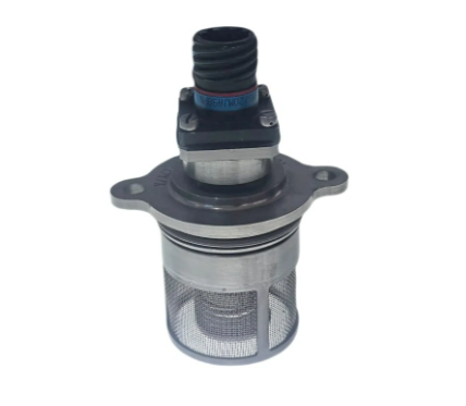
Aviation hydraulic networks power flight-critical systems. They control landing gear deployment, flight surface actuation, and nose-wheel steering. A sudden actuator or pump failure poses severe safety risks mid-flight. Unscheduled downtime disrupts fleet operations and causes cascading logistical delays. We must catch wear early to maintain operational readiness and protect passengers.
Traditional inline filters restrict flow to protect downstream components. They trap everything indifferently, which complicates analysis. You cannot easily access or analyze the trapped materials without cutting the filter open. Generic sensors measure overall fluid quality but lack failure specificity. A dedicated debris collector targets the exact mechanical problem. It captures specific metal fragments. It retains them safely for detailed metallurgical analysis. You can inspect the actual debris to determine exactly which bearing or gear is failing. This precise isolation is crucial for accurate root cause analysis.
You must establish clear success criteria for your implementation. A successful monitoring program completely transforms your maintenance outcomes. Consider these primary goals:
Zero unpredicted pump failures during standard operational flight cycles.
Minimized maintenance hours spent on routine fluid line inspections.
Verifiable audit trails supporting strict aviation compliance and safety audits.
Rapid isolation of faulty components before secondary downstream damage occurs.
We see many operators fail because they rely solely on bulk fluid sampling. Fluid analysis takes days to process in an off-site lab. Real-time capture provides immediate, actionable evidence directly on the flight line.
Optimized magnetic circuits are vital for accurate detection. They must capture specific sizes and masses of ferromagnetic debris. High hydraulic flow rates threaten to wash particles away before the magnet secures them. Engineers often use advanced rare-earth magnets, such as samarium-cobalt, to ensure maximum pull force even at high temperatures.
We need robust capture efficiency across all operating conditions. The device must grab critical spallation flakes generated by severe bearing fatigue. At the same time, it should ignore benign, microscopic wear "fuzz." Finding this balance prevents false alarms while catching real threats. A common mistake is selecting a magnet that is excessively strong. Overly powerful magnets capture harmless atmospheric dust and normal wear particles, creating constant nuisance alerts. You want a magnetic field precisely optimized for macroscopic debris.
The probe design directly impacts hydraulic line pressure. Bulky probes cause excessive pressure drops within the fluid lines. Engineers must minimize this restriction to maintain system efficiency. Fluid must flow smoothly around the sensor tip without creating turbulent dead zones where debris might hide.
Housing materials matter significantly in aerospace applications. Aerospace-grade titanium or aluminum alloys offer excellent weight-to-strength ratios. They also provide robust corrosion resistance against aggressive synthetic hydraulic fluids. Titanium excels in high-pressure environments, while aluminum suits weight-critical installations. You must select the material based on the specific pressure rating of the installation zone.
Visual-inspection models require manual removal. Technicians look at the magnet physically during scheduled walk-arounds. This method is highly reliable but depends entirely on consistent human intervention. If a technician misses a check, a catastrophic failure might go unnoticed.
Electrical models bridge a gap to trigger automated alerts. They send signals straight to a cockpit display or a central maintenance panel. This functionality makes the aviation chip detector far more responsive. It enables real-time fault detection during flight.
However, electrical contacts face harsh operational challenges. High-vibration environments can disrupt these sensitive signals. Engineers must design secure, ruggedized connections. Best practices dictate using vibration-damped mountings to ensure signal reliability during severe atmospheric turbulence.
Modern fleets rely heavily on integrated data architectures. Advanced detectors feed continuous or periodic data into a Health and Usage Monitoring System (HUMS). This integration shifts maintenance from reactive fixes to predictive schedules. You can plan component replacements long before a mid-air emergency occurs.
Trend analysis changes everything we know about failure prediction. We no longer rely on simple binary "chip/no chip" alerts. Instead, algorithms monitor the precise rate of debris accumulation over operating hours. A sudden spike in the collection rate indicates an imminent failure. Slow, steady accumulation might simply indicate normal component break-in wear. By analyzing this data delta, maintenance teams can ground an aircraft exactly when necessary.
Integrating an oil sensor suite yields profound diagnostic value. Combining particle capture mechanisms with fluid quality monitoring provides a holistic picture of hydraulic health. You can easily isolate complex mechanical issues. For example, you can distinguish pump cavitation from mechanical bearing wear. Cavitation degrades the fluid without producing large metal flakes. Bearing wear produces distinct structural shards. Using both data points ensures accurate troubleshooting and prevents unnecessary parts replacement.
A common mistake during integration is ignoring data sampling rates. If your system checks sensor status too infrequently, you might miss a rapid degradation event. Ensure your HUMS polls the sensor at intervals appropriate for the specific hydraulic circuit's criticality level.
Skepticism often surrounds nuisance alarms in aviation maintenance. "Wear fuzz" frequently washes over electrical contacts. This fine, harmless dust can create a false ground, triggering a cockpit alert. Pilots lose confidence in monitoring systems when false alarms occur regularly, leading to alert fatigue.
Modern systems combat this issue cleverly. They use active pulse-burn mechanisms. A short electrical burst melts away microscopic fuzz without triggering an alarm. It acts like a tiny targeted fuse. They also rely on precise physical gap tolerances. The distance between the magnetic poles is engineered carefully. Non-critical dust cannot bridge this specific gap, effectively preventing false grounding events.
Self-closing valve housings are absolutely non-negotiable for practical maintenance. They feature an auto-shutoff mechanism integrated directly into the housing body.
Technicians must remove the magnetic probe for visual or lab inspection. They cannot drain the entire hydraulic reservoir just to check one sensor. They also cannot introduce dangerous air pockets into high-pressure lines. Self-closing designs seal the fluid path instantly upon probe removal. This allows for clean, rapid, and safe line-level inspections. Always ensure mechanics keep the housing O-rings properly lubricated to prevent weeping during insertion.
Aviation safety demands rigorous, standardized testing. Components must meet strict FAA or EASA certification rules before flight approval. You cannot legally install uncertified hardware on commercial or military aircraft.
They must pass comprehensive DO-160 environmental testing. This standard proves they can survive extreme vibration, shock, and temperature fluctuations. Defense standard qualifications also apply to military applications. Meeting these standards guarantees the sensor will not fail under severe operational stress. Always request full qualification test reports from your chosen manufacturer before finalizing a purchase.
Choosing the correct equipment requires a systematic approach. You must map your systems, evaluate vendors, and conduct real-world testing. This disciplined process prevents costly procurement mistakes and ensures flight safety.
System Mapping: You must identify optimal placement locations across your aircraft. Place detectors on pump return lines or directly at case drains. This strategy maximizes capture rates before debris enters the main reservoirs. Once debris reaches the reservoir, it settles or disperses, making detection nearly impossible.
Sensor Installation Locations Comparison
| Installation Location | Capture Efficiency | Detection Speed | System Impact |
|---|---|---|---|
| Case Drain | Very High | Immediate | Minimal pressure drop |
| Main Return Line | High | Fast | Moderate pressure drop |
| Reservoir Bottom | Low (Settling occurs) | Slow | Zero pressure drop |
| Pressure Filter Housing | Moderate | Delayed | High integration complexity |
Vendor Capabilities: Evaluate the manufacturer carefully. Look for historical reliability data and field-proven case studies. Verify their custom housing engineering skills. Ensure they offer reasonable lead times for specialized aerospace-grade materials. A reliable vendor should act as a proactive engineering partner, not just a passive parts supplier.
Proof of Concept: Always test before authorizing full fleet deployment. Follow these systematic steps to validate performance:
Request detailed flow-bench testing data from the manufacturer.
Review the false-alarm mitigation statistics for the specific model.
Initiate a pilot installation on a small, controlled subset of the fleet.
Monitor the false-alarm rates during actual flight operations.
Validate the capture efficiency by inspecting the probes at scheduled intervals.
This proof of concept confirms that the selected model performs flawlessly in your specific operational environment.
Selecting the right magnetic chip detector requires careful consideration. You must balance magnetic efficiency, robust mechanical design, and seamless maintenance integration. A well-chosen sensor transforms hidden wear into visible, actionable data.
We recommend prioritizing devices equipped with self-closing valves. They minimize inspection friction and keep your high-pressure fluids secure. You should also maximize your diagnostic yield by integrating these sensors directly into predictive maintenance frameworks like HUMS. This combination ensures maximum uptime and safety for your aircraft.
Take action today to protect your assets. Audit your current hydraulic return-line filtration systems immediately. Request technical data sheets and detailed failure-mode analyses from qualified aviation sensor manufacturers. Upgrading your monitoring strategy is the most effective way to eliminate unpredicted hydraulic failures.
A: Capture size depends heavily on flow velocity and the inherent magnetic strength. However, most units are optimized for macroscopic particles. They typically target fragments 100 microns and larger. These larger flakes are highly indicative of active spalling or severe metal fatigue. This targeted capture effectively separates critical structural degradation from normal, microscopic break-in wear.
A: Placement in the return line is highly effective. However, installing it specifically at the case drain of hydraulic pumps yields the best results. This strategic location ensures debris is caught immediately after generation. It secures the metal fragments before they can disperse into the reservoir or get trapped by secondary inline filtration systems.
A: Engineers carefully size the physical gap between the magnetic poles. This sizing prevents small dust from completing the circuit. Additionally, advanced systems use optional "fuzz-burning" electrical circuits. These circuits deliver a small pulse to safely melt away microscopic, non-critical debris. This process maintains clear signal integrity without missing large, dangerous metal flakes.


