
Views: 0 Author: Site Editor Publish Time: 2026-10-08 Origin: Site
Asset-intensive industries face a persistent, costly vulnerability. Heavy equipment runs constantly, yet operators only conduct fluid health checks periodically. This massive time lag between periodic lab-based oil analysis and actual catastrophic machinery failure remains a critical blind spot. You cannot rely solely on offline sampling to catch rapid mechanical degradation. Transitioning to continuous, real-time sensing closes this dangerous gap. This shift protects mission-critical assets from sudden breakdowns.
We will examine the functional realities, technical limitations, and the business case for implementing the ML-1 architecture. This article details how continuous oil debris monitoring transforms maintenance strategies. You will learn how to evaluate specific integration realities and navigate complex hydraulic considerations. Ultimately, we map out a practical deployment path to seamlessly upgrade your predictive maintenance program.
Technology Gap: Traditional lab analysis leaves blind spots in machinery health; real-time monitoring closes this gap by detecting abnormal wear generation instantly.
Detector Differentiation: Unlike standard optical sensors, inductive/magnetic sensors (like the ML-1 type) are unaffected by oil opacity, aeration, or fluid degradation.
Integration Reality: Successful deployment requires specific hydraulic considerations (flow rates, bypass vs. full-flow) and seamless data integration with existing SCADA or condition monitoring software.
ROI Metric: The primary evaluation metric is the reduction of secondary catastrophic damage and the elimination of unnecessary preventative teardowns.
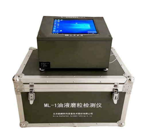
Industrial maintenance teams have relied on interval-based oil sampling for decades. This traditional method provides excellent data on chemical degradation. However, it severely limits your ability to catch sudden mechanical wear. Rapid-onset fatigue wear, such as spalling and pitting, happens fast. These destructive events often initiate and escalate entirely between monthly or quarterly oil sampling intervals. A gear tooth can begin to crack and shed large metal flakes within a matter of days. If your next lab sample is three weeks away, the gearbox will likely destroy itself before you ever see the report.
You must also consider the cost of false negatives when relying exclusively on other monitoring methods. Many reliability programs lean heavily on vibration analysis. While vibration monitoring is essential, it sometimes detects faults too late in the failure curve. On the widely recognized P-F (Potential to Functional failure) curve, heavy wear particle generation often precedes detectable vibration changes. By the time a bearing vibrates enough to trigger an alarm, severe internal damage has already occurred. You lose the window for a minor repair and face a major overhaul.
Defining success criteria is critical for any technology upgrade. A successful machinery monitor upgrade must provide actionable, early-warning data. It must do this without generating high volumes of false-positive alarms. Alarm fatigue is a real threat in industrial environments. If a sensor constantly triggers warnings for normal operating conditions, operators will eventually ignore it. Real-time monitoring succeeds only when the alerts accurately reflect severe, abnormal wear events.
Understanding the available sensor technologies helps you make informed procurement decisions. The market offers two primary categories for monitoring oil cleanliness and wear debris. They operate on fundamentally different physics and serve very different primary use cases.
Most basic fluid cleanliness sensors use optical technology. A conventional particle counter uses lasers or light blockage methods to count particles. Fluid flows through a narrow channel. A laser beam passes through the fluid and hits a photo-detector. When a particle blocks the light, the sensor registers a voltage drop and counts a particle. This method excellently measures overall fluid cleanliness according to ISO 4406 standards.
However, optical sensors suffer from severe drawbacks in heavy industrial applications. They have high susceptibility to false alarms. Air bubbles (aeration) block light exactly like solid particles. Water ingress scatters the laser beam, creating massive spikes in particle counts. Furthermore, optical sensors fail in "dark" oil. Heavily oxidized, sooty, or heavily dyed gear oils absorb the laser light. The sensor becomes entirely blind. You cannot rely on optical technology to monitor severe mechanical wear in harsh gear or bearing applications.
To overcome optical limitations, heavy industry relies on inductive sensors. We can look at the functional mechanics of an ML-1 detector as a prime example of an inline metallic debris sensor. These devices use advanced electromagnetic fields instead of light.
The mechanism is elegant and robust. The fluid flows through a specialized metallic coil. This coil generates a continuous high-frequency magnetic field. When a metallic particle passes through this field, it creates a disturbance. The sensor registers this specific electromagnetic disturbance.
The advantages of this technology are substantial. Inductive sensors ignore all non-metallic contaminants. Air bubbles, water droplets, and dirt simply pass through the magnetic field without registering. The oil opacity does not matter. Furthermore, advanced units actively differentiate between ferrous and non-ferrous wear debris. They achieve this by measuring the phase shift of the signal. Ferrous particles (iron, steel) increase the magnetic inductance. Non-ferrous particles (brass, copper, aluminum) decrease it through the generation of eddy currents. This allows you to pinpoint whether a steel gear or a bronze cage is failing.
| Evaluation Metric | Optical Laser Counters | Inductive/Magnetic Sensors |
|---|---|---|
| Detection Principle | Light blockage / scattering | Electromagnetic field disturbance |
| Aeration & Water Sensitivity | Highly susceptible (causes false positives) | Completely immune |
| Oil Opacity Limits | Fails in dark, sooty, or heavily oxidized oil | Unaffected by fluid color or degradation |
| Material Differentiation | Cannot distinguish material types | Separates ferrous from non-ferrous metals |
| Primary Application | General fluid cleanliness monitoring | Catastrophic machine failure prevention |
When evaluating a wear particle detector ml 1, engineering teams must look beyond basic spec sheets. You need to map technical features directly to reliability outcomes. Proper evaluation ensures the hardware actually protects the asset in real-world conditions.
Particle size sensitivity is the most critical feature to evaluate. You are not looking for background rubbing wear. Normal operating wear generates particles between 1µm and 10µm. Real-time debris sensors target severe, abnormal wear modes. Evaluate the minimum detectable micron size. A robust sensor might detect 40µm for ferrous particles and 135µm for non-ferrous particles. You must relate this sensitivity to actual severe wear modes like gear spalling or bearing flaking. These failure modes shed large chunks of metal. Detecting a 50µm steel flake instantly gives you the early warning needed to shut down the machine before catastrophic failure occurs.
You must assess how the sensor handles extreme operational environments. Check the maximum pressure ratings and operating temperature bands. Industrial hydraulic systems often spike in pressure. The sensor manifold must withstand these surges without leaking or failing.
Fluid viscosity limits require special attention. As a transparent assumption, high-viscosity gear oils at low temperatures present a major challenge. Thick, cold oil creates immense flow resistance. Pushing cold ISO VG 320 gear oil through a small sensor orifice can restrict flow or trigger false readings. You may require specific sensor manifold designs, wider internal bores, or localized heating elements to ensure reliable data during cold starts.
Hardware is useless if the data remains trapped on the plant floor. You must evaluate the output formats carefully. Modern sensors typically offer multiple industrial protocols. You should look for Modbus TCP/RTU, 4-20mA analog outputs, or CAN bus compatibility. These standard protocols ensure seamless integration with your existing SCADA systems or condition monitoring dashboards.
Security considerations are equally important. Piping sensor data from edge hardware into enterprise cloud dashboards introduces cyber risk. You must work with IT to secure these connections. Use edge gateways with strong encryption. Consider air-gapping the local sensor network from the wider corporate network. Proper data architecture ensures actionability without compromising plant security.
Buying the sensor is only the first step. The physical installation determines whether the project succeeds or fails. Poor hydraulic integration will ruin the most advanced sensor technology.
You face a choice between inline installation and offline bypass loops. Examine the risks carefully. Inline installation places the sensor directly in the main lubrication flow. This guarantees the sensor sees all the oil. However, it creates potential flow restriction risks. If the sensor clogs, you might starve a critical bearing of lubrication.
Offline installation, often called a kidney loop, provides a safer alternative. You pull oil from the reservoir, pass it through the sensor, and return it. This removes the risk of flow restriction to the main asset. However, you must maintain turbulent flow in the bypass piping. Heavy metal particles settle quickly in slow-moving fluids. If the flow is laminar and slow, the dangerous 100µm steel flakes will drop out of suspension before they ever reach the sensor. Designing the piping to maintain high fluid velocity prevents this settling.
Expect some noise during the initial startup. A newly installed oil wear detector will register initial "legacy" debris. Most industrial gearboxes hold historical wear particles trapped in low-flow areas or stuck to internal walls. Changing flow dynamics during installation often kicks up this old debris. Address the necessity of a flushing period. Run the system for several days to clear out historical particles. You must establish a baseline calibration before setting any hard alarm thresholds. Setting alarms too early will result in immediate false positives.
Every piece of monitoring equipment requires its own maintenance. Discuss the self-checking capabilities of modern sensors with your vendor. Advanced units monitor their own internal coil health and report diagnostic errors. Determine the interval required for physical inspection or cleaning. Even with bypass loops, sludge can accumulate. Ensuring the lubrication sensor itself does not become a point of failure is paramount. Schedule brief visual inspections of the sensor manifold during regular preventive maintenance routes.
Transitioning to real-time debris monitoring requires a methodical approach. Do not attempt to upgrade your entire facility at once. Strategic implementation proves the value and refines the installation process.
Advise your engineering teams to avoid full-fleet rollouts initially. These large projects often stall due to integration complexity. Instead, recommend deploying the sensor on a single, mission-critical asset. Choose a high-failure-rate machine. A critical wind turbine gearbox, a massive primary crusher main bearing, or a boiler feed pump makes an excellent pilot subject. Proving the technology on a difficult asset secures management buy-in for future expansion.
Use a strict checklist when evaluating vendors. Do not rely solely on marketing brochures. Ask these specific questions:
Data Access: Does the vendor provide open API access, or do they require you to buy proprietary, locked-down software? Always favor open data protocols.
Validation: Are field calibration certificates provided with the hardware? You need proof the unit meets its stated sensitivity limits.
Reliability: What is the empirical Mean Time Between Failures (MTBF) of the sensor unit? Industrial sensors must survive years of vibration and heat.
Support: Does the vendor offer direct engineering support for complex hydraulic integrations?
Define a clear pathway to move forward. First, request technical data sheets for the specific sensor models. Compare their viscosity and temperature limits against your asset's operating profile. Next, initiate a pilot site survey. Walk the machine with a hydraulic specialist to identify the best tapping points for a kidney loop. Finally, consult with an integration engineer to map out the data flow from the sensor to your control room. Taking these measured steps ensures a successful implementation.
Moving to a real-time debris monitoring architecture fundamentally changes how you manage asset health. It is less about buying new hardware and more about shifting your maintenance strategy from reactive to highly predictive. You stop waiting for scheduled lab reports and start acting on live mechanical data. This approach protects your most valuable equipment from catastrophic secondary damage.
While inductive detectors require careful hydraulic integration and thoughtful baseline calibration, the effort pays off immensely. They offer unparalleled reliability in harsh, heavily contaminated environments. Compared to fragile optical alternatives, inductive technology provides the rugged, accurate data needed to keep heavy industry running safely.
A: Yes, inductive and magnetic principles are completely blind to air bubbles and water droplets. Because the sensor relies on electromagnetic field disturbances rather than light blockage, it removes the primary source of false positives seen in traditional optical counters.
A: The fluid must maintain a minimum velocity to keep heavy metal particles suspended. If the fluid flow is too slow or laminar, large particles may settle out of the fluid stream before they reach the sensing coil, resulting in missed detections.
A: No. It replaces the need for frequent, interval-based sampling solely for detecting large wear debris. However, periodic lab analysis remains highly recommended for assessing chemical degradation, measuring fluid viscosity, and verifying additive package depletion.


